PortoBallast Vessel-to-Shore Connection Checklist
Updated
A containerised treatment facility needs an engineered vessel-to-shore interface, not just a hose between two flanges. Review the water route, nominal connections, pressure and flow, hose geometry, shore utilities, isolation, communication and sampling arrangements. PortoBallast's August 2026 brochure supplies reference tie-in data; the actual offered unit, vessel drawings and berth survey must determine the connection package and operating controls.
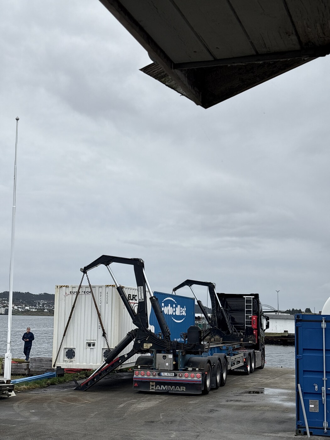
Sea Clean port-side treatment and PortoBallast hub
Key takeaways
- Draw the entire source-to-outlet route, including any bypass or wrong-discharge path.
- DN200 is a reference size, not a complete coupling specification.
- Review pressure, hose geometry, vessel movement and component ratings.
- Verify electrical and auxiliary requirements against the actual supplied unit.
- Agree a coordinated start/stop process and communication-loss response.
- Include sampling, residue handling, disconnection and records in the initial plan.
Map the complete water route before selecting hoses
Identify the source ballast tanks, vessel pumps, relevant valves, vessel-side connection, reception inlet, process route and final destination. Show any route by which water could bypass the intended facility or reach an incorrect outlet. A simple connection sketch helps vessel and shore teams compare their understanding before installation, and gives the required authorities a clearer view of what is being proposed.
Include proposed sampling points, drainage and any temporary storage or alternative outlet. Describe which parts of the route are permanent and which are temporary. The manufacturer launch mentions different possible treated-effluent destinations, but those possibilities do not make every outlet permissible at a particular berth. The accepted route must be identified before a transfer starts, not improvised when the container has been unloaded.
Check nominal size, connection standard and pressure together
The August brochure lists DN200 inlet/outlet for the treatment unit. DN200 is a nominal connection reference; it does not specify every detail needed to mate a hose or adapter to the delivered equipment and vessel. Obtain the actual drawings, connection standard, sealing arrangement, orientation and allowable loads. An adapter should be selected from those facts, not from an assumption that all DN200 connections are identical.
Review available pump pressure, accepted process flow, hose and coupling ratings, line losses and the consequence of a closed valve or sudden stop. The brochure's treatment-unit pressure row lists a maximum/minimum of 10 bar/1 bar, but that is not a substitute for the limits of the complete temporary transfer assembly. The most restrictive component or operating condition must be accounted for by the responsible engineering and operating parties.
Related guidance: PortoBallast Specifications: Flow, Power and Footprint
Survey hose routing, movement and berth geometry
Measure the practical route rather than only the straight-line distance between connection points. Include quay edges, changes in height, obstructions, vehicle paths, safe bends, connection access and areas where hoses need protection or support. Allow for the vessel's movement and the expected changes in freeboard during cargo or ballast operations. Hose weight and mechanical loading must not be transferred to an unsuitable connection.
Identify where the team can inspect the line and where a leak, obstruction or disconnection would be difficult to reach. Port and terminal rules may restrict crossings or require additional protection and permits. A mobile facility's location should be chosen with the whole route in mind: the shortest hose is not necessarily the safest route, and a convenient parking space may block operator access or emergency response.
Confirm electrical supply and auxiliary utilities
The treatment-unit brochure lists 116 kW and 400 V three-phase, four-wire plus ground. Confirm the actual electrical documents, available site supply, protection, safe cable route, earthing, isolation and responsibility for making the connection. Do not assume that a berth outlet or a hired generator is adequate because its nominal voltage matches. Electrical installation and operation require the appropriately competent responsible parties.
The brochure also lists DN25 fresh water with 1 bar pressure head, DN50 drainage and compressed air at 6 bar/300 L/min through DN15, noting the air equipment is included in the system. Check the delivered scope and the water and drainage arrangements. The dosing skid has its own supply information. Utility preparation should reflect what is actually installed, rather than multiplying brochure figures into unverified external service requirements.
Agree isolation, communication and stop-work responsibilities
Name the vessel and shore people who authorise start-up, control valves and pumps, observe the treatment process and act on a stop request. Agree the communication method and the response to communication loss. A stop signal must produce an understood safe state across the whole interface, not merely switch off the shore equipment while the vessel continues pumping into a closed or unsuitable path.
Before operation, use the actual procedures to check line-up, the intended outlet, readiness of process monitoring and the actions required for abnormal conditions. Include safeguards against mixing unrelated tanks, transferring water outside the accepted scope or restarting after an unresolved alarm. This article is a planning checklist, not a valve-by-valve operating instruction or a substitute for the manufacturer's manual and the site risk assessment.
Related guidance: PortoBallast for a BWTS Breakdown: Contingency Planning
Plan sampling, disconnection and handover from the start
If sampling is needed, identify representative and accessible points, the intended analysis, timing, responsible sampling party and custody requirements. Sampling access must be compatible with a safe transfer. Decide in advance whether any hold, repeat test or operating interruption affects the sequence. A convenient drain tap is not automatically a representative regulatory sampling location for every purpose.
At close-out, record transfer periods, volume basis, process evidence, interruptions, sampling references and any outstanding work. Isolation, depressurisation, draining, cleaning and disconnection must follow the agreed safe method. Confirm the destination of residual water and any solids, restore the vessel and berth to the agreed condition and retain the handover documents. A complete interface plan includes the end of the operation, not just the first connection.
Frequently asked questions
Does PortoBallast use DN200 connections?
The August 2026 brochure lists DN200 inlet/outlet for its treatment unit. The delivered unit and vessel drawings still need checking for connection standard, sealing, orientation, pressure rating and the required hose or adapter package.
Can the vessel use its existing ballast pump?
That needs engineering and operational review. Available flow and pressure, line losses, pump control, the treatment envelope and the weakest component in the transfer assembly all matter. A matching nominal pipe size does not establish compatibility.
Does a mobile container need substantial shore power?
The brochure lists a 116 kW, 400 V three-phase supply specification for the treatment unit. Confirm the actual electrical design, protection and supplied configuration. A generic berth outlet must not be assumed suitable without assessment.
Can this checklist replace an operating procedure?
No. It identifies planning questions for the actual vessel, facility and site. The responsible parties need the manufacturer's instructions, drawings, risk assessment and agreed port conditions to produce the specific operating and emergency procedures.
Sources
- Euro Tech — PortoBallast brochure, August 2026 edition — Pages 2–4: process, tie-ins, technical envelope and dosing system; manufacturer data subject to change, not Sea Clean's as-built acceptance record.
- Euro Tech Holdings — mobile hybrid launch, 9 June 2026 — Issuer's announcement: Nasdaq CLWT, containerised terminal/barge deployment and trailer transport.
- Euro Tech Holdings — Sea Clean partnership announcement, 17 June 2026 — Names Sea Clean and the planned Norwegian coastal facility. Its dispatch forecast is not the actual receipt date.
- IMO — Ballast Water Management — Convention, management plans, discharge standards and the distinction between equipment approval and operational requirements.
Related articles
- PortoBallast Specifications: Flow, Power and Footprint
- Deploying a Containerised BWTS at Ports and Terminals
- PortoBallast for a BWTS Breakdown: Contingency Planning
- PortoBallast, IMO D-2 Testing and Port Acceptance
- What Is a Ballast Water Port Reception Facility?
- Port-Side Ballast Water Treatment for Vessels
Discuss PortoBallast directly by email
Training, rental/operated service and contingency enquiries are reviewed individually. Include objectives or the vessel, installed BWMS, port, dates, water volume and scope. Availability, readiness, suitability, permissions and quotation require confirmation. These links prepare email drafts; no website submission inbox is used.
Explore the PortoBallast series
- First container received: 7 October 2026
- What is PortoBallast, and who is Euro Tech?
- Specifications: flow, power and footprint
- Sea Clean's planned training facility
- Rental periods and service scope
- BWTS breakdown contingency planning
- IMO D-2, testing and port acceptance
- TRO neutralisation versus full treatment
- Filtration, UV and sludge management
- Deployment at ports and terminals
- Mobile treatment versus onboard BWMS