Containerised Ballast Water Treatment for Ports
Updated
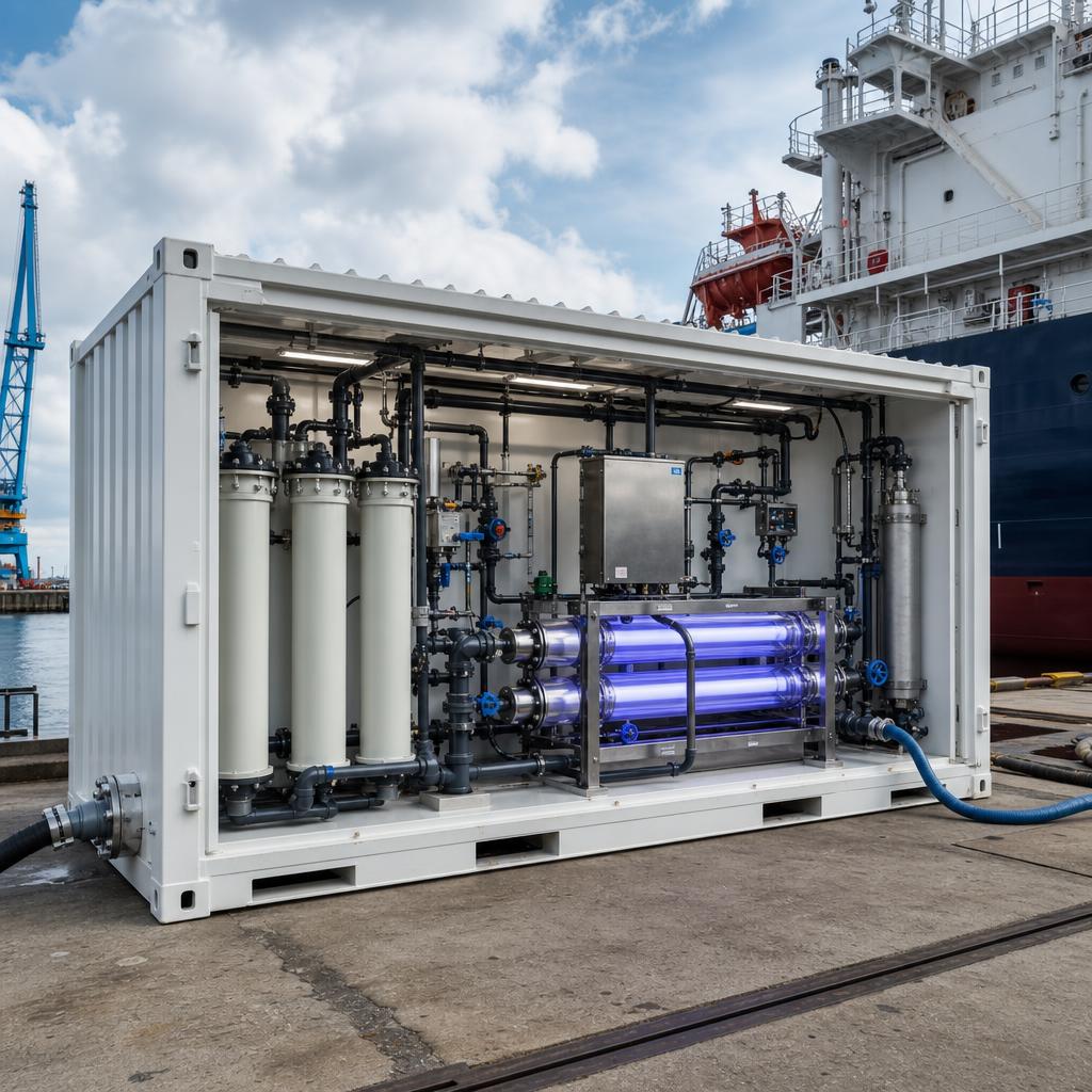
A containerised system packages treatment equipment into a transportable module that can be located near a suitable berth or utility point. It reduces some civil works, but it does not remove the need to verify site loads, connections, drainage, power, hydraulics and acceptance.
Key takeaways
- Containers reduce some civil work but remain site-dependent installations.
- Water, power, drainage and controls need defined connection boundaries.
- Solids loading affects filtration and waste arrangements.
- The final discharge route needs its own permit and hydraulic check.
- Parallel modules increase capacity but multiply operational interfaces.
- Commissioning evidence should precede operational use.
Select the deployment location
Container location planning is the starting point for the project brief. In this case, shorter connections reduce hose exposure and pressure loss. Establish quay loading, crane access, flood level and separation from cargo work before comparing concepts, because these conditions determine whether shore-side work is practical.
The commercial case should be measured against the operating pattern rather than an equipment headline. Record quay loading, crane access, flood level and separation from cargo work alongside expected vessel demand, turnaround pressure and the consequence of an unavailable service. That creates a basis for deciding whether the option should be mobile, permanent or not pursued.
A feasibility note should state the assumptions that could change the conclusion. In particular, revisit quay loading, crane access, flood level and separation from cargo work when berth allocation, vessel mix or local rules change. This prevents a preliminary concept from being treated as an operational commitment.
Define module interfaces
Container interfaces needs a physical walk-through, not just a drawing review. a modular package still needs clear water, power, drain and control boundaries. Inspect connection sizes, voltage, earthing, communications and isolation valves at the actual berth and include the people who will rig, monitor and disconnect the transfer.
Temporary interfaces should be designed for the full transfer sequence. Check connection sizes, voltage, earthing, communications and isolation valves for safe access, containment, mechanical protection and an unambiguous isolation point. A route that works while idle may be unsuitable during cargo work or an emergency.
The operating procedure should identify who controls each boundary. It should cover connection sizes, voltage, earthing, communications and isolation valves, communications between ship and shore, and the action to take after a leak, pressure alarm or loss of contact. Those details matter more than nominal connection compatibility.
Protect the treatment train
Pre-treatment planning must be calculated as a complete system rather than as a nameplate flow. water quality and solids loading can affect filtration and maintenance demand. Use screening needs, differential pressure alarms and solids collection to establish the duty point over the expected range of vessel levels and transfer rates.
Pressure loss changes with hose length, fittings, filtration condition and elevation. Confirm screening needs, differential pressure alarms and solids collection using conservative fouling and operating assumptions, then agree the allowable setpoints with the vessel. This avoids forcing a shore service into a pump condition it cannot sustain.
Instrumentation should show whether the planned duty is actually being achieved. Trend screening needs, differential pressure alarms and solids collection with transfer volume, pressure and alarms, and preserve the data after the operation. It is the most useful evidence when a delay or abnormal stop needs explaining.
Check discharge routing
Final discharge routing includes supporting systems that can be overlooked in an early layout. treated water cannot simply be directed to the nearest drain. Assess outfall permission, drainage capacity, sampling point and backflow protection as part of the treatment package, rather than leaving it for site mobilisation.
A workable installation provides safe access for inspection, cleaning and fault response. Verify outfall permission, drainage capacity, sampling point and backflow protection under normal work, night work and restricted terminal conditions. The layout should not depend on improvised cables, drains or access routes.
The design basis should also define what happens when a support service is lost. Test outfall permission, drainage capacity, sampling point and backflow protection against a power interruption, blocked drain, high solids load or control failure. A controlled stop is preferable to continuing a transfer without the required safeguards.
Use scalable capacity carefully
Modular capacity planning is governed by the local operating and acceptance framework. parallel modules can increase availability but also add interfaces and operators. Confirm berth demand profile, pump sequencing and utility headroom early with the parties whose approval, permit or instruction affects the work.
IMO G5 is guidance for reception facilities; it is not a licence or a universal technical design. Map berth demand profile, pump sequencing and utility headroom against applicable flag, port, class, authority and discharge-permit requirements. The resulting gap list should be closed before a vessel is booked.
No port-side arrangement should be described as guaranteeing D-2 compliance or acceptance. Retain the decisions on berth demand profile, pump sequencing and utility headroom, the agreed operating limits and the authority communications. That record makes the limits of the service clear to all parties.
Prepare commissioning evidence
Site acceptance preparation turns a completed transfer into an auditable operation. a container arrival does not prove a complete operational service. Agree functional checks, calibration records, training and authority-required documentation before work starts so evidence is captured at the time it is created.
Useful records connect the vessel's ballast activity with shore actions and any separated-waste route. Reconcile functional checks, calibration records, training and authority-required documentation against timestamps, meter totals, alarms and the person responsible for each handover. Corrections made later are weaker than contemporaneous records.
Sampling or testing, where required, needs an agreed purpose and chain of responsibility. Sea Clean can coordinate with independent ISO 17025 laboratories and flag/class-authorised parties where required; it is not an accredited laboratory or independent certifier. Store functional checks, calibration records, training and authority-required documentation with the service report and relevant vessel documentation.
Frequently asked questions
Are containerised systems permanent?
They can be temporary, relocatable or semi-permanent depending on site design. Their operating permissions and utility interfaces must still be established for the selected location.
What utilities are typically needed?
Requirements vary by design, but power, earthing, drainage, communications and safe access commonly need assessment. Confirm the exact package requirements during engineering.
Can a container discharge to terminal drainage?
Only where the drainage route, capacity and permissions support it. Backflow, sampling and the final receiving point need review.
Does modular equipment avoid permitting?
No. A transportable form factor does not remove local permit or acceptance requirements. The authority basis should be confirmed project by project.