Ballast Water Reception Facility Terminal Design
Updated
A reception terminal design must combine vessel connections, hydraulic duty, treatment boundaries, utilities and safe operating access. Layout decisions should be tested against real berth windows and waste-handling responsibilities.
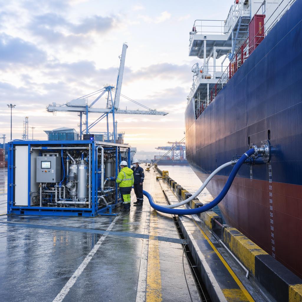
Key takeaways
- Start with how the terminal will connect to and serve its intended vessel mix rather than selecting equipment first.
- Verify vessel connections, pressure limits, hose routing and berth access as one hydraulic interface.
- Check applicable flag, port, class, authority, discharge-permit and approval requirements project by project.
- Use catalog capacities only for screening; complete project-specific hydraulic, utility, permitting and acceptance assessment.
- Allocate vessel, terminal, operator, waste and evidence responsibilities in a written interface matrix.
- Prove the operation with reconciled records, defined sampling and a controlled readiness review.
Define the operating case for ballast water reception facility terminal design
Terminal design begins with a berth-by-berth service envelope, not a generic building footprint. The key decision is how the terminal will connect to and serve its intended vessel mix. Use actual call data and berth rules, not an annual-volume average, to establish the design case.
Separate planned service from a vessel contingency request. They have different notice periods, crew interfaces and tolerance for a missed berth slot. The operating procedure should say who supplies vessel data and who has authority to accept the job.
Treat safe physical access at the berth and manifold as a fixed design input. It should be visible in the survey record, risk register and procurement scope. That prevents a technically plausible concept from becoming unusable at the berth.
Resolve the physical and hydraulic interface
Fix manifold reach, pipe-rack crossings, drainage falls and emergency access in the civil layout. Trace the route from vessel manifold to treatment boundary and final discharge or receiving point. Show isolation, vents, drains, sample points and temporary equipment on the same line diagram.
Calculate pressure loss at the operating range through hoses, fittings, meters, strainers and the treatment train. Compare the result with both vessel pump capability and shore-side pressure limits. A nominal pump capacity is not a workable duty point until this check is complete.
Design connection, flushing and drain-down as operational tasks. Hose lifting, drip containment, vehicle segregation and emergency egress must work in the actual berth layout. A pre-job connection checklist makes those constraints visible to vessel and terminal teams.
Specify the process and control boundary
Separate dirty drainage and solids handling from clean utility and control spaces. State where raw transfer ends, where pre-filtration and treatment begin, and where any discharge monitoring applies. Applicable flag, port, class, authority, discharge-permit and approval requirements must be verified project by project.
PACT's public port page describes mobile and containerised treatment for ocean-going vessels with or without onboard BWMS. It is useful for option screening, not an acceptance statement for a particular operation. Sea Clean AS is PACT Marine's European partner; that relationship is not an automatic approval.
Specify electrical supply, earthing, drainage, communications, lighting and safe shutdown before fixing the layout. Control narratives should assign alarm response and restart authority. The vessel must know which indications and stop signals apply across the interface.
Test capacity and service resilience
Select duty and standby arrangements around the terminal's maximum simultaneous calls. Calculate net service rate after setup, verification, ramp-up, interruptions, flushing and demobilisation. Test the resulting schedule against overlapping calls and the longest credible connection route.
The 2021 HarborBallast catalog presents indicative trailer/mobile service at 50–500 m³/h, fixed-location service at 50–5,000 m³/h, and mobile barge service at 1,000–5,000 m³/h. These dated values are not Sea Clean capacity promises, approvals or a substitute for engineering. Project-specific hydraulic, utility, local-permitting and acceptance assessment is required.
Write a stop-work procedure for weather, traffic restrictions, alarms and missed berth slots. It should state the safe condition of hoses, equipment and retained water. Name the vessel and terminal contacts who receive the decision and record it.
Assign custody, monitoring and records
Allocate vessel readiness, terminal access, connection work, treatment operation, sample custody, waste handling and release authority in an interface matrix. The matrix must also name stop-work authority. A service record without ownership is difficult to defend or improve.
Use P&IDs, cause-and-effect charts and custody boundaries as design deliverables. The records must demonstrate the terminal duty, operating limits and accountable handovers. Reconcile time-stamped flow, pressure, alarms and connection status with the vessel's ballast activity.
Agree sampling locations, containers, chain of custody and report format before work starts. Sea Clean can coordinate with independent ISO 17025 laboratories and flag/class-authorised parties where required. Neither a treatment provider nor commissioning work automatically replaces authority-required evidence.
Turn the concept into a controlled operation
Freeze the layout only after operator walk-throughs and authority interface reviews. Move through desktop screening, berth survey, interface design, authority engagement and a controlled trial. Each stage should close a named uncertainty before procurement or routine service.
Tender documents should request duty points, utility assumptions, drawings, limits, maintenance, training and data outputs. Require explicit exclusions for civil work, cranes, hoses, waste disposal and communications. Compare lifecycle operability as well as capital cost.
Rehearse call-out, handover and stop-work actions with vessel, terminal and service personnel. Review actual setup time, access control, communications and record quality. Revise the procedure before declaring routine readiness.
Frequently asked questions
What is the first step in ballast water reception facility terminal design?
Begin with the vessel envelope and the berth survey. The terminal footprint follows safe connection, drainage and access requirements.
Can a port-side system be assumed to meet D-2 requirements?
No. IMO G5 is guidance, not a terminal licence or one-size-fits-all design. Local requirements still govern.
What evidence should the operator retain?
Retain approved drawings, design duty points, utility studies, operating limits and handover procedures. Link revisions to the as-built record.
Can Sea Clean arrange testing support?
Sea Clean can coordinate required third-party sampling or testing support. Laboratory and authority roles must be defined in advance.